Difference between revisions of "Direct Stiffness Method"
(Created page with "by Katie Lundgren and Eric Jenkins External edit by Lucas McGill __TOC__ ==Introduction== image:StuartburnTrussBridge.jpg|right|thumb|250px|Truss Bridge in Gardenton, Man...") |
|||
| Line 199: | Line 199: | ||
In addition to the initial loading and displacement vectors, a master stiffness matrix, K, is constructed. A master stiffness matrix is generated by combining the two elements' globalized matrices. The following is the MATLAB driver function for generating the two elements' global-coordinate stiffness matrices and merging them into a master stiffness matrix: | In addition to the initial loading and displacement vectors, a master stiffness matrix, K, is constructed. A master stiffness matrix is generated by combining the two elements' globalized matrices. The following is the MATLAB driver function for generating the two elements' global-coordinate stiffness matrices and merging them into a master stiffness matrix: | ||
| − | <matlab>%*********************************************************************** | + | <syntaxhighlight lang="matlab">%*********************************************************************** |
% function AssembleMasterStiffOfExTruss | % function AssembleMasterStiffOfExTruss | ||
% | % | ||
| Line 216: | Line 216: | ||
% element 2: E = 1000 A = 4 | % element 2: E = 1000 A = 4 | ||
Ke = ElemStiff2DTwoNodeBar(0, 3, 4, 0, 1000, 4); | Ke = ElemStiff2DTwoNodeBar(0, 3, 4, 0, 1000, 4); | ||
| − | K = MergeElemIntoMasterStiff(Ke, [3,4,5,6], K);</ | + | K = MergeElemIntoMasterStiff(Ke, [3,4,5,6], K);</syntaxhighlight> |
After assembling the master stiffness matrix, displacement boundary conditions are placed on nodes (1) and (3), which restrict movement in these ground-hinged nodes. Then the force vector, f, is modified to become fmod. fmod accounts for pre-described displacements in any of the nodal elements. In our case, neither of the ground nodes will have any kind of pre-described displacements. | After assembling the master stiffness matrix, displacement boundary conditions are placed on nodes (1) and (3), which restrict movement in these ground-hinged nodes. Then the force vector, f, is modified to become fmod. fmod accounts for pre-described displacements in any of the nodal elements. In our case, neither of the ground nodes will have any kind of pre-described displacements. | ||
| Line 224: | Line 224: | ||
The following is the main MATLAB driver function for solving this truss structure problem: | The following is the main MATLAB driver function for solving this truss structure problem: | ||
| − | <matlab>function driver | + | <syntaxhighlight lang="matlab">function driver |
% Function driver | % Function driver | ||
% Driver function to find the nodal displacements, reaction forces, and | % Driver function to find the nodal displacements, reaction forces, and | ||
| Line 257: | Line 257: | ||
% displacements, u. | % displacements, u. | ||
fprintf('\nInternal member forces:') | fprintf('\nInternal member forces:') | ||
| − | p = IntForcesOfExampleTruss( u )</ | + | p = IntForcesOfExampleTruss( u )</syntaxhighlight> |
MATLAB's output from running driver.m : | MATLAB's output from running driver.m : | ||
Latest revision as of 15:28, 16 February 2021
by Katie Lundgren and Eric Jenkins External edit by Lucas McGill
Introduction
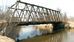
This Wiki is meant to give you just a taste of structural engineering by presenting a crash-course in using the Direct Stiffness Method for structural analysis. Below, you will read about the analysis of simple 2-dimensional truss structures. These same techniques are used in real-world applications, such as truss-bridge design!
Structural Analysis
Structural analysis is the computation of deflections, deformations, and internal forces or stresses on and within static structures. Structural analysis methods allow one to both analyze the strength of existing structures as well as predict the strength of structures in design. Engineers use various standard methods in the design of structures such as bridges, buildings, roadways, and pipelines. But these methods of analysis we will address can also be applied to structures of much smaller or larger scales - everything from the durability of a microchip to the safety of a coal mine. Analysis requires input data, including (but not limited to) structural geometry, support conditions, and structural loads. Output can include reactions, stresses, and displacements that result from the input.
In any form of structural analysis, simplifications, or 'idealizations', must be made to structures to analyze them mathematically. When designing a bridge, structural engineers cannot predict every wind storm, earthquake, or material defect that may weaken the strength of the structure. So assumptions must be made, and factors of safety must be applied to account for uncertainty in design.
Material Science
Any material can fail with enough applied stress. However, predicting strength can be difficult, since defects in a material's design are unpredictable and inevitable. In addition to production defects, a material's durability can be affected by outside factors, like weather and age. Aluminum, for example, loses structural strength every time it undergoes stress changes, even if the stresses are magnitudes lower than the material's failing ultimate strength. This is why airplanes must be constantly checked for signs of wear.
The vast majority of structural analysis and design considers only the linear-elastic range of a material's strength behavior. Linear elasticity means that there is a direct linear relationship between the amount of force applied and deflection, and any deformation caused from stresses in this range are temporary and recoverable. If a force is applied to a steel beam causing it to deflect, then halving the applied force will half the beam's deflection. This linear-elastic property holds true until the applied stress reaches yield stress. Yielding is the point at which the material begins to deform irreversibly and non-linearly. Yielding strength is typically much lower than the material's breaking point, but structural designers generally attempt to keep structures in this region of linear load-deformation response.
Finite Element Method
The finite element method (FEM) is a simple and efficient method of finding a numerical approximation for a mathematical model of a structure. It involves taking a complex problem and decomposing it into pieces upon each of which a simple approximation of the solution may be constructed, and then putting the local approximate solutions together to obtain a global approximate solution.
Direct Stiffness Method
The direct stiffness method (DSM) is the most common implementation of the FEM. It is particularly used for computer-automated analysis of complex structures. The method begins with breaking down the model of the complex structure into simpler idealized parts. These material stiffness properties of these parts are then individually evaluated. The behavior of the entire idealized structure is determined by compiling the stiffness equations of the smaller parts into one single matrix equation.
The DSM process can be broken down into three major steps: Breakdown, Assembly, and Solution. These three major steps are outlined below. In this Wiki, we will focus specifically on 2-dimensional truss structures. Trusses are assumed to only transmit forces in compression and tension, which simplifies the idealization process greatly. In a truss structure, all ends are pinned, meaning these hinges are free to rotate, but they can still be restricted from horizontal and vertical movement.
Breakdown
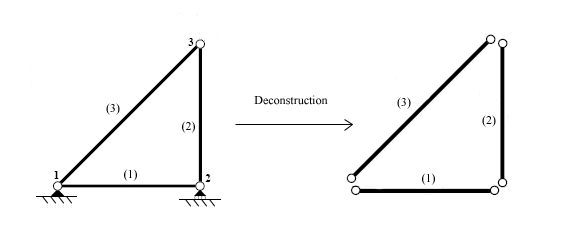
There are three main sub-steps in the Breakdown process: Disconnection, Localization, and Member Formation. First, individual elements in the structure must be identified. The structure can then be broken down into individual elements, separated at the structure's nodes, the points which hold the elements together:
Each member can then be analyzed individually. In 2-dimensional truss analysis, each end of the truss can have two degrees of freedom (corresponding to horizontal and vertical displacement).
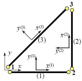
Analysis of a truss member is done with respect to its localized coordinate system. In the triangular truss system shown above, elements (2) and (3) do not line up with the structure's global coordinate system. Deformations and reaction forces will be computed relative to the local member and later converted to the global coordinate system, as seen in the following section, Assembly.
The basic 2D global->local coordinate transformation scheme can be derived by four basic equations that relate local horizontal and vertical coordinates to the global system, where represents an element's global coordinate displacement vector, and represents the same element displacement vector in local coordinates:
These local<-->global transformations are geometrically-derived relations that lay the basis for a general transformation matrix: or where T is the transformation matrix:
Once displacements in the individual element are calculated, the truss's reaction forces at its two nodes can be found with a linear displacement->force relationship. Forces on a truss can be related to the truss's resulting displacement using a stiffness matrix:
In local coordinate analysis, force and elongation can be expressed in terms of joint forces and displacements:
This leads to the stiffness matrix necessary for relating an element's elongation to its joint forces:
,
where E is the element's elastic modulus, A is its cross-sectional area, and L is its length.
Assembly
Assembly involves two sub-steps: globalization and merging.
Globalization is through which the member stiffness equations are transformed back to the global coordinate system. Relations connecting joint displacements and forces in the local and global coordinate systems can be established in terms of transformation matrices.
Now that the local<-->global coordinate transformation is understood, an element's stiffness matrix, K, can be re-written in terms of global coordinates:
Once the member stiffness equations are written in terms of global coordinates, they can be merged into a stiffness matrix of the complete structure.
Knowing that , we can merge multiple elements into a larger stiffness matrix, a force vector, and a displacement vector that represent all of the nodes of the structure, all in global coordinates:
,
where n represents the total number of elements in the structure.
Solution
Once the master stiffness equation has been formed, a method can be chosen for solving it.
Solving for the overall structure's unknown reaction forces and resulting nodal displacements is a simple matter of solving for the unknowns in the global structure's force-displacement relation, .
See the following section for an example of this algorithm, carried out step-by-step with MATLAB.
Example Problem
This is a sample problem taken from Exercise 3.7 of Felippa's Finite Element Methods book.
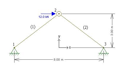
Consider the two-member arch-truss structure shown below. Take span S = 8, height H = 3, elastic modulus E = 1000, cross section areas A(1) = 2 and A(2) = 4, and horizontal crown force P = 12, as shown here.
Problem
Compute nodal displacements, nodal reaction forces, and internal truss forces for the structure above.
Solution
The two-truss structure is held together at three nodes: two on the ground (nodes 1 and 3) and one node that connects member (1) to member (2) (node 2).
Nodes 1 and 3 are stationary, and can have no displacements in the x or y direction. However, node 2 is not affixed to ground and is free to move as a result of any imposed forces. The hinged nodes 1 and 3 cannot move and instead transfer any forces imposed on the structure into the ground as reactions, expressed in x-y vector components - the same way displacements are express in x-y vector components.
MATLAB Direct Stiffness analysis begins by creating a global force vector, f, which represents the degrees of freedom of each of the nodes that compose our structure. Since our structure has three nodes and each node has two 2-dimensional degrees of freedom (x and y), the master force and displacement vectors, f and u, respectively, will contain 6 elements:
and
where the reaction forces at nodes 1 and 3 and the displacement at node 2 are initially unknown.
In addition to the initial loading and displacement vectors, a master stiffness matrix, K, is constructed. A master stiffness matrix is generated by combining the two elements' globalized matrices. The following is the MATLAB driver function for generating the two elements' global-coordinate stiffness matrices and merging them into a master stiffness matrix:
%***********************************************************************
%  function AssembleMasterStiffOfExTruss
%
%  Forms the 6x6 global stiffness matrix of the example problem
%***********************************************************************

function K = AssembleMasterStiffOfExTruss

% global matrix
K = zeros(6);

% element 1:  E = 1000 A = 2
Ke = ElemStiff2DTwoNodeBar(-4, 0, 0, 3, 1000, 2);
K = MergeElemIntoMasterStiff(Ke, [1,2,3,4], K);

% element 2:  E = 1000 A = 4
Ke = ElemStiff2DTwoNodeBar(0, 3, 4, 0, 1000, 4);
K = MergeElemIntoMasterStiff(Ke, [3,4,5,6], K);
After assembling the master stiffness matrix, displacement boundary conditions are placed on nodes (1) and (3), which restrict movement in these ground-hinged nodes. Then the force vector, f, is modified to become fmod. fmod accounts for pre-described displacements in any of the nodal elements. In our case, neither of the ground nodes will have any kind of pre-described displacements.
Finally, solution vectors can be obtained. Vector u corresponds to the final nodal displacements, vector f corresponds to reactional forces at the nodes, and vector p corresponds to the trusses internal reaction forces. All values are relative to the global coordinate system specified in the above figure.
The following is the main MATLAB driver function for solving this truss structure problem:
function driver
% Function driver
% Driver function to find the nodal displacements, reaction forces, and
% internal truss forces of Felippa Exercise 3.7.

% Set up a global force vector, corresponding to the x and y values of
% each of the three nodes to be analyzed, and save it to variable f.
f = [0; 0; 12; 0; 0; 0];
% Assemble the master stiffness matrix, K, and save it to variable K
K = AssembleMasterStiffOfExTruss;
% Modify the global K matrix to impose Displacement Boundary Conditions -
% [1, 2, 5, 6] restricts x- and y- movement for nodes 1 and 3.
Kmod = ModifiedMasterStiffForDBC( [1, 2, 5, 6], K);
% Modify the global load vector to impose homogeneous displacement BCs - in
% our case, there will be no pre-described nodal displacements.  So the two
% ground hinge nodes, 1 and 3 - which correspond to elements 1, 2, 5, and 6
% in the force and displacement vectors - will all be set to 0.
fmod = ModifiedMasterForceForDBC( [1, 2, 5, 6], [0, 0, 0, 0], f, K);

fprintf('\nComputed nodal displacements:')
% Since Kmod is symmetric and positive definite, operator \ calls
% chol(Kmod) and do a forward and back substitution, solving
% Kmod * u = fmod for u, the global displacement vector.
u = Kmod\fmod

% Multiply the resulting global node displacements by the master stiffness
% matrix, K, to compute the resulting node reaction forces.
fprintf('\nExternal node forces including reactions:')
f = K * u

% Calculate the internal forces of the two trusses, based on global node
% displacements, u.
fprintf('\nInternal member forces:')
p = IntForcesOfExampleTruss( u )
MATLAB's output from running driver.m :
>> driver

Computed nodal displacements:
u =

         0
         0
    0.0176
    0.0078
         0
         0


External node forces including reactions:
f =

   -6.0000
   -4.5000
   12.0000
         0
   -6.0000
    4.5000


Internal member forces:
p =

    7.5000
   -7.5000
As seen from MATLAB's output above, elements 3 and 4 of the 6-element displacement vector u have non-zero values, which correspond to Node 2 horizontal displacement and Node 2 vertical displacement, respectively:
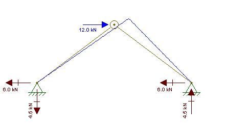
Node 2 is displaced 0.0176 m in the positive x-direction and 0.0078 m in the positive y-direction.
Nodal reaction forces are also listed in MATLAB's output for vector f:
The first two elements correspond to reactions at Node 1: 6 to the left and 4.5 down. The third element of f, 12, corresponds to the pre-defined horizontal force at Node 2. Finally, the last two elements of vector f, -6 and 4.5, refer to the reactions at Node 3: 6 to the left and 4.5 up.
Finally, MATLAB outputs its result for the internal forces in the two trusses as vector p, tension-positive:
The first element of vector p, 7.5, refers to the magnitude of reaction tensile force in Truss (1). The second element, -7.5, refers to the magnitude of compressive force in Truss (2).
Software analysis using F-Tool confirms our resulting displacements and reaction forces in the hinges, as shown below:
This example is clearly a very light sample of how the Direct Stiffness Method can be used to analyze truss structures. But the method is identical no matter how complicated the truss system may be.
A Note on the Indeterminate Nature of Structures
By Lucas McGIll. Many simple truss problems like the one above can be solved in a few minutes merely by hand. That is, simply summing the forces and moments to solve for the reactions. A problem arises when there are more constraints than equilibrium equations. If the truss is over constrained, then the system of equations is deemed indeterminate. The beauty of this method, however, is that indeterminate can still easily be solved. For this reason, the DSM is used in many computer packages to quickly solve for deflection, forces, stress, etc. by generating meshes on not only truss structures but also solid parts.
Relevant MATLAB Files
The following are links to the MATLAB files necessary for running analysis of this example truss.
AssembleMasterStiffOfExTruss.m
Conclusion
The Direct Stiffness Method is a fairly straightforward algorithm that can be used to compute reactional forces, internal forces, and displacements in individual members of a structure. More complicated applications of the DSM involve complex structures in 2D or 3D that can carry distributed loads across members, carry moments, and carry rotational torsion. DSM is probably the most efficient way to quickly design buildings and structures for various purposes. All thanks to derivations and modifications from Finite Element Methods.
References
Felippa, Carlos A. Introduction to Finite Element Method. 2001. University of Colorado. <Available online here>
Martha, Luis Fernando. Ftool - Two-dimensional Frame Analysis Tool
Wikipedia.org - Direct Stiffness Method
Wikipedia.org - Finite Element Method
Wikipedia.org - Structural Analysis
Special thanks to Professor C. Armando Duarte and to the U of I TAM and CEE departments!
